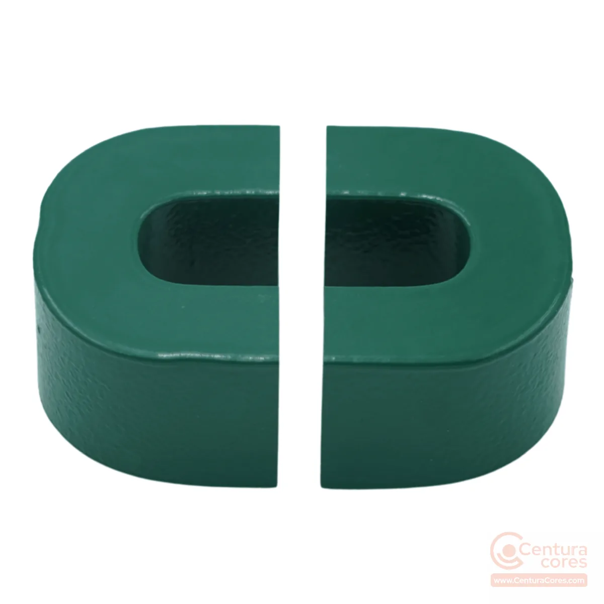
Nanocrystalline cut core 19×24×83×35×63.5×122×2 mm
19×24×83×35×63.5×122×2 mm nanocrystalline cut core, Green Epoxy.
CCNC-19-24-83-35-63P5-122-002-MFGR is a 19×24×83×35×63.5×122×2 mm nanocrystalline cut core for solar string/central inverter reactors, EV charging station reactors, and industrial motor-drive DC chokes. The 19×24 mm limb and 83 mm window length suit bobbin or form-wound coils where an openable core simplifies assembly. Choose this size when Ae, window, and overall length (122 mm) match the target inductor or reactor duty.
Technical Specifications
Physical dimensions
Magnetic properties
Finish and handling
Environmental
Applications and selection
Applications
- solar string/central inverter reactors
- EV charging station reactors
- industrial motor-drive DC chokes
- UPS output reactors
- high-power EV fast-charging station reactors (typically 10–30kW+ per module class)
- solar central/string inverter output filters
- commercial UPS DC-link chokes
- heavy industrial motor-drive reactors
- high-power traction converter chokes
When to choose this size
This 19×24×83×35×63.5×122×2 mm cut core (Ae 6.12 cm²) is aimed at solar string/central inverter reactors and related choke or reactor designs. Step down to the 13×15×56×25×42×84×2 mm core when a smaller envelope and lower mass are enough for the inductance and current. This is the largest published cut-core option: pick it for high-power EV, solar, or industrial reactor stages. In short, pick CCNC-19-24-83-35-63P5-122-002-MFGR when your design for solar string/central inverter reactors fits this limb and window; pick a neighbor when power level or envelope shifts the trade-off.
Winding notes
Magnetic calculations should use Ae 6.12 cm² and Le 26.7 cm with the published a–f×R geometry (19×24×83×35×63.5×122×2 mm). The cut faces (gap view, R=2 mm) must mate cleanly after winding; keep clamping consistent to avoid gap variation and audible noise. Nanocrystalline cut cores suit gapped or low-reluctance inductor designs within 1.25 Tesla and -40°C to +130°C; stay inside the epoxy coating temperature capability for continuous duty.
Related application guides
Frequently asked questions
What do the a–f dimensions mean?
Published geometry uses a (tongue width 19 mm), b (build 24 mm), c (window length 83 mm), d (strip width 35 mm), e (window height 63.5 mm), and f (overall length 122 mm), with corner radius R=2 mm. Use Ae and Le with this geometry for magnetic design.
Is this cut core suitable for chokes and reactors?
Yes. CCNC-19-24-83-35-63P5-122-002-MFGR is typically used for solar string/central inverter reactors, including high-power EV fast-charging station reactors (typically 10–30kW+ per module class). The openable cut-core form simplifies bobbin winding and assembly compared with a closed toroid.
When should I choose a different size instead?
Stay with this size for higher-power reactor duty. Step down to the 13×15×56×25×42×84×2 mm core only when mass and envelope must shrink.
Related products
Nanocrystalline cut core 13×15×56×25×42×84×2 mm
CCNC-13-15-56-25-42-84-002-MFGR
13×15×56×25×42×84×2 mm
View CCNC-13-15-56-25-42-84-002-MFGR specsNanocrystalline cut core 11×12.5×29.5×20×35×53×2 mm
CCNC-11-12P5-29P5-20-35-53-002-MFGR
11×12.5×29.5×20×35×53×2 mm
View CCNC-11-12P5-29P5-20-35-53-002-MFGR specsNanocrystalline cut core 11×13×40×20×35.5×63×2 mm
CCNC-11-13-40-20-35P5-63-002-MFGR
11×13×40×20×35.5×63×2 mm
View CCNC-11-13-40-20-35P5-63-002-MFGR specsNeed this core for your application?
Get pricing, availability, and winding support for CCNC-19-24-83-35-63P5-122-002-MFGR.