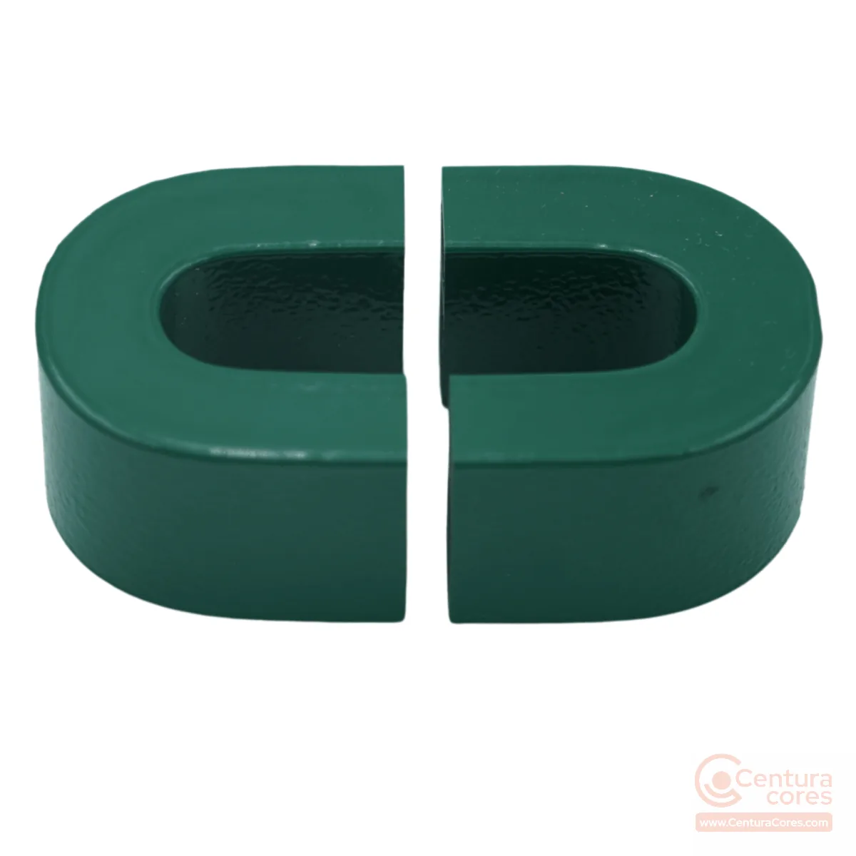
CCNC-09-09-32-15-28-51-002-MFGR
In stockNanocrystalline cut core 9×9×32×15×28×51×2 mm
9×9×32×15×28×51×2 mm
AL 205 µH/T² @ 1 kHz
From $29.00
View CCNC-09-09-32-15-28-51-002-MFGR specsPrecision-cut nanocrystalline C-cores for PFC boost inductors, EV onboard chargers, solar string inverters, and DC reactors. Matched cut pairs with published a–f geometry, AL, and production photos.
CenturaCores nanocrystalline cut cores are openable C-shaped pairs cut from high-permeability ribbon and epoxy-coated for handling. The openable path simplifies bobbin winding and lets you set a controlled air gap for DC-biased inductors where a closed nanocrystalline toroidal core would be harder to wind or would saturate under bias.
Compared with ferrite, nanocrystalline offers higher saturation (about 1.25 T) and lower core loss in the tens-of-kHz band used by PFC and onboard charger stages. Compared with CRGO, it stays efficient at switcher frequencies where silicon steel runs hot. See our nanocrystalline vs CRGO vs ferrite guide for material trade-offs.
Every stocked SKU publishes a–f×R dimensions, Ae/Le, AL at 1 kHz / 10 kHz / 100 kHz, pack pricing, and photos of the gap face, assembled pair, lamination edge, and QC checks. Custom gap, stack, and AL targets are available via request a quote.
Matched cut pairs with published a–f dimensions, AL values, and production photos. Buy online or open a product page for gap, assembled, caliper, scale, and lamination views.
CCNC-09-09-32-15-28-51-002-MFGR
In stock9×9×32×15×28×51×2 mm
AL 205 µH/T² @ 1 kHz
From $29.00
View CCNC-09-09-32-15-28-51-002-MFGR specs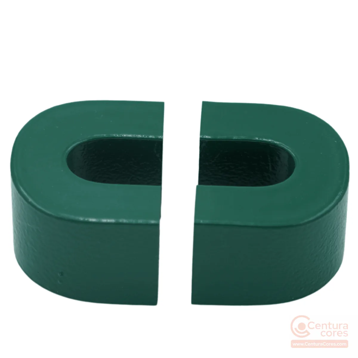
CCNC-10-10-33-20-31-53-002-MFGR
In stock10×10×33×20×31×53×2 mm
AL 310 µH/T² @ 1 kHz
From $35.00
View CCNC-10-10-33-20-31-53-002-MFGR specs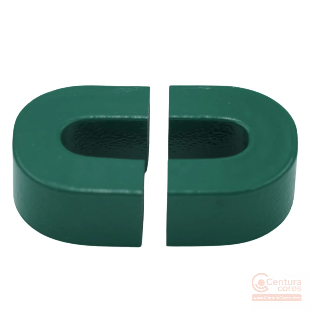
CCNC-11-12P5-29P5-20-35-53-002-MFGR
In stock11×12.5×29.5×20×35×53×2 mm
AL 330 µH/T² @ 1 kHz
From $36.00
View CCNC-11-12P5-29P5-20-35-53-002-MFGR specs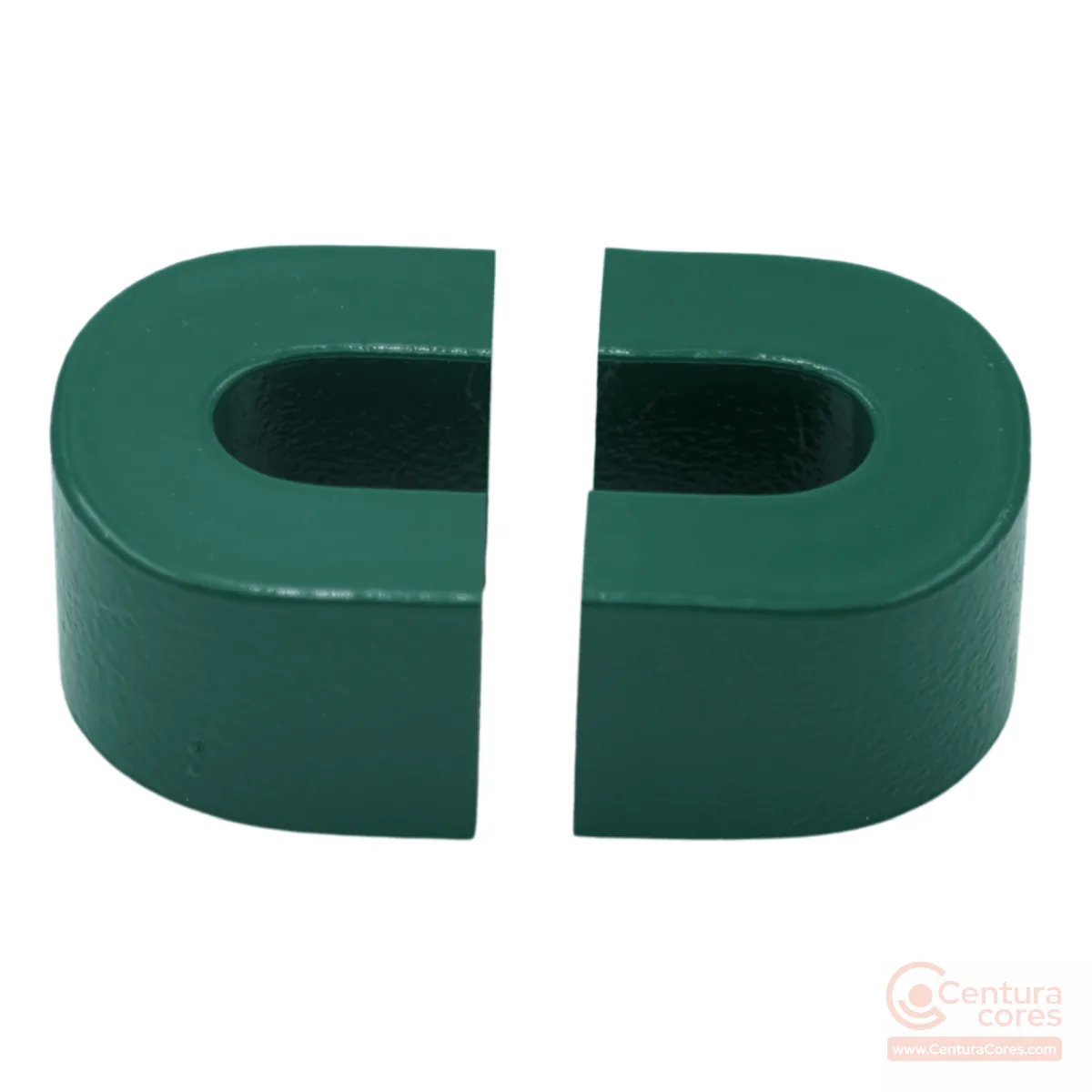
CCNC-11-13-40-20-35P5-63-002-MFGR
In stock11×13×40×20×35.5×63×2 mm
AL 270 µH/T² @ 1 kHz
From $39.00
View CCNC-11-13-40-20-35P5-63-002-MFGR specs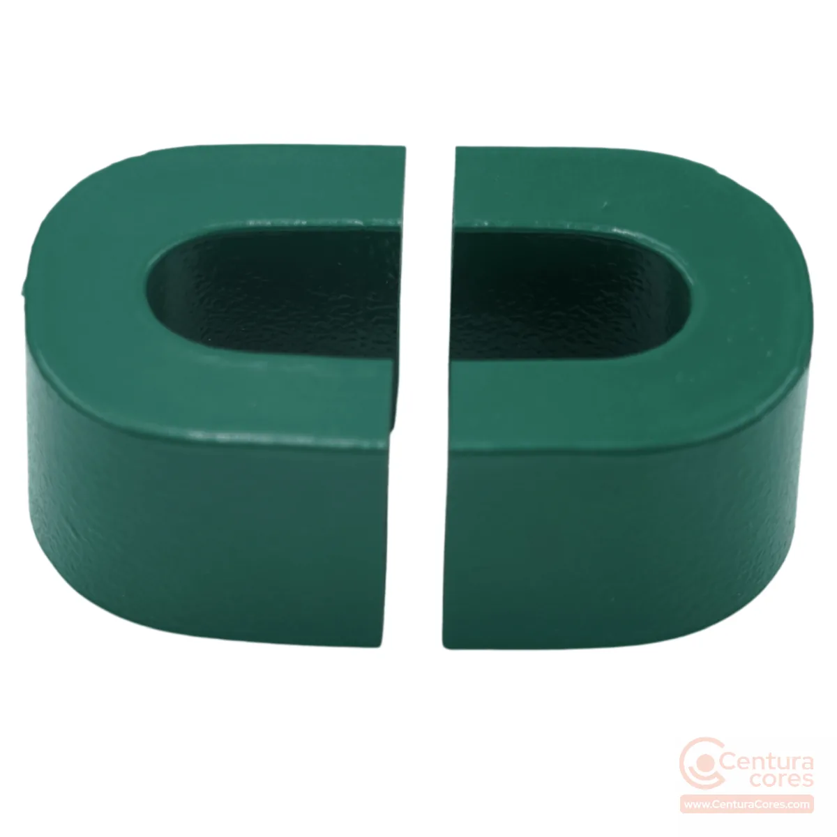
CCNC-10P8-13-40P5-25-35P5-62-002-MFGR
In stock10.8×13×40.5×25×35.5×62×2 mm
AL 370 µH/T² @ 1 kHz
From $55.00
View CCNC-10P8-13-40P5-25-35P5-62-002-MFGR specs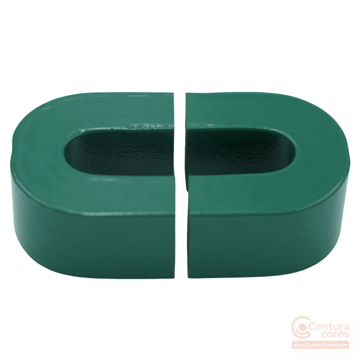
CCNC-13-15-56-25-42-84-002-MFGR
In stock13×15×56×25×42×84×2 mm
AL 350 µH/T² @ 1 kHz
From $72.00
View CCNC-13-15-56-25-42-84-002-MFGR specs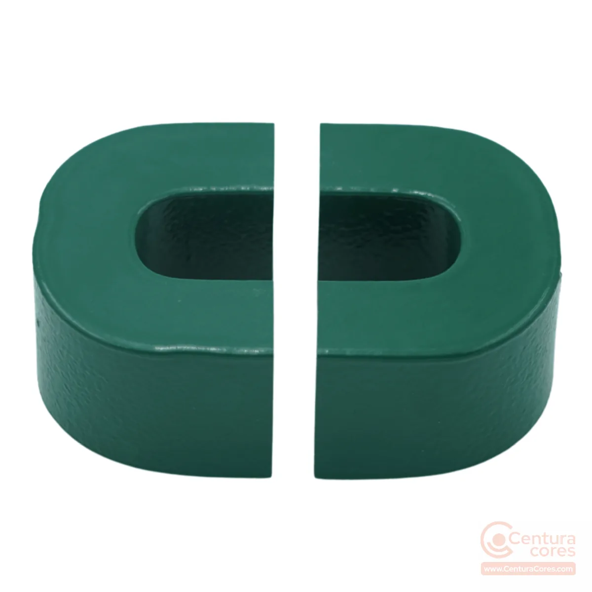
CCNC-19-24-83-35-63P5-122-002-MFGR
In stock19×24×83×35×63.5×122×2 mm
AL 400 µH/T² @ 1 kHz
From $137.00
View CCNC-19-24-83-35-63P5-122-002-MFGR specsEach size is a matched cut pair with published a–f dimensions, AL at 1 kHz / 10 kHz / 100 kHz, and production photos. Need a custom gap or stack? Request a quote.
| SKU | a×b×c×d×e×f×R (mm) | AL @ 1 kHz | Typical use |
|---|---|---|---|
| CCNC-09-09-32-15-28-51-002-MFGR | 9×9×32×15×28×51×2 mm | AL 205 µH/T² @ 1 kHz | LED driver chokes, small SMPS output inductors |
| CCNC-10-10-33-20-31-53-002-MFGR | 10×10×33×20×31×53×2 mm | AL 310 µH/T² @ 1 kHz | DC-DC converter output chokes, small telecom power inductors |
| CCNC-11-12P5-29P5-20-35-53-002-MFGR | 11×12.5×29.5×20×35×53×2 mm | AL 330 µH/T² @ 1 kHz | compact PFC boost inductors, LED driver inductors |
| CCNC-11-13-40-20-35P5-63-002-MFGR | 11×13×40×20×35.5×63×2 mm | AL 270 µH/T² @ 1 kHz | DC filter reactors, mid-range SMPS output inductors |
| CCNC-10P8-13-40P5-25-35P5-62-002-MFGR | 10.8×13×40.5×25×35.5×62×2 mm | AL 370 µH/T² @ 1 kHz | DC-link reactors, PFC inductors |
| CCNC-13-15-56-25-42-84-002-MFGR | 13×15×56×25×42×84×2 mm | AL 350 µH/T² @ 1 kHz | industrial PFC inductors, DC reactors |
| CCNC-19-24-83-35-63P5-122-002-MFGR | 19×24×83×35×63.5×122×2 mm | AL 400 µH/T² @ 1 kHz | solar string/central inverter reactors, EV charging station reactors |
Nanocrystalline cut core 9×9×32×15×28×51×2 mm
AL 205 µH/T² @ 1 kHz
View CCNC-09-09-32-15-28-51-002-MFGR specsNanocrystalline cut core 10×10×33×20×31×53×2 mm
AL 310 µH/T² @ 1 kHz
View CCNC-10-10-33-20-31-53-002-MFGR specsNanocrystalline cut core 11×12.5×29.5×20×35×53×2 mm
AL 330 µH/T² @ 1 kHz
View CCNC-11-12P5-29P5-20-35-53-002-MFGR specsNanocrystalline cut core 11×13×40×20×35.5×63×2 mm
AL 270 µH/T² @ 1 kHz
View CCNC-11-13-40-20-35P5-63-002-MFGR specsNanocrystalline cut core 10.8×13×40.5×25×35.5×62×2 mm
AL 370 µH/T² @ 1 kHz
View CCNC-10P8-13-40P5-25-35P5-62-002-MFGR specsNanocrystalline cut core 13×15×56×25×42×84×2 mm
AL 350 µH/T² @ 1 kHz
View CCNC-13-15-56-25-42-84-002-MFGR specsNanocrystalline cut core 19×24×83×35×63.5×122×2 mm
AL 400 µH/T² @ 1 kHz
View CCNC-19-24-83-35-63P5-122-002-MFGR specsGapped nanocrystalline cut cores handle the DC bias in continuous-conduction PFC boost stages used in EV charger and power cores and industrial SMPS. Higher Bs than ferrite keeps the core smaller for the same peak flux.
Use cut cores for EV charging station reactors, OBC DC inductors, and solar string inverter filter/reactor stages where window area and gap control matter more than a closed toroid path.
Low high-frequency core loss reduces hotspot temperature versus ferrite at the same induction. Keep clamping consistent so gap variation does not shift AL or create audible noise. Quote custom gap when your L and Ipeak need a different AL than the stocked pair.
Stocked CCNC parts ship as matched pairs with published AL. For designs that need a larger gap (more DC bias headroom) or a tighter gap (higher AL), CenturaCores can cut and finish to target inductance. Provide frequency, Lmin/Lmax, DC bias, Ae preference, and max temperature when you request a custom cut-core quote.
Size the inductor with the transformer / inductor core designer or compare materials in the material selection article.
Choose a cut core when you need an openable magnetic path for bobbin or form-wound coils, a controlled air gap for DC bias (PFC boost inductors, DC reactors), or easier production winding than a closed toroid. Use a PBT-cased toroid for common-mode chokes, CTs, and closed-path EMI designs where the winding stays on a continuous ring.
Yes. Published AL values assume the as-shipped matched cut pair. For PFC boost inductors, EV onboard charger reactors, and solar string inverter stages, we can quote custom gap, stack height, and AL targets. Request a quote with your frequency, inductance, DC bias, and thermal limits.
Nanocrystalline typically delivers much lower core loss than ferrite at tens of kHz with higher saturation (about 1.25 T), and far lower high-frequency loss than CRGO. That combination suits compact PFC boost inductors, EV charger reactors, and DC reactors where ferrite would saturate or run hot and CRGO would be oversized at switcher frequencies.
Published magnetics cover roughly -40°C to +130°C continuous design space, with Curie temperature near 560°C. Stay within the epoxy coating temperature class for continuous duty, and account for hotspot rise from copper and core loss when designing clamps and bobbins.
Published geometry uses a (tongue width), b (build), c (window length), d (strip width), e (window height), f (overall length), and R (corner radius), all in mm. Use Ae and Le with that geometry for magnetic design. Each product page lists AL at 1 kHz, 10 kHz, and 100 kHz with production photos of the gap, assembled pair, and lamination edge.
Engineering notes by Manoj Kumar, Founder & Chief Technologist at CenturaCores.
Share your PFC, EV charger, or solar inverter inductor targets and we will match a stocked CCNC size or quote a custom cut.