Core Design
Nanocrystalline Cut Cores: The R&D Backbone for PFC and Fast Prototyping
Quick answer
A closed nanocrystalline toroid is an excellent magnetic path. It is a poor prototyping tool when you need a bobbin, foil, or a known air gap. Openable C-cores are the R&D backbone because you wind the coil on a standard machine, assemble the halves, set the gap, and reopen the core after the first bench test without destroying the winding.
Power designers chasing higher density at tens of kilohertz already know the material trade. CRGO saturates high but runs hot as eddy currents climb. Ferrite stays efficient at high frequency, then saturates around 0.4 T, so the core grows or the design is flux-starved under DC bias. Nanocrystalline sits in the middle: saturation around 1.27 T, useful permeability, and low core loss in the 10–100 kHz band used by PFC boost inductors, onboard chargers, and solar inverter reactors. The geometry is what turns that material into a part you can iterate in an afternoon.
The size ladder is the backbone, not a product shot
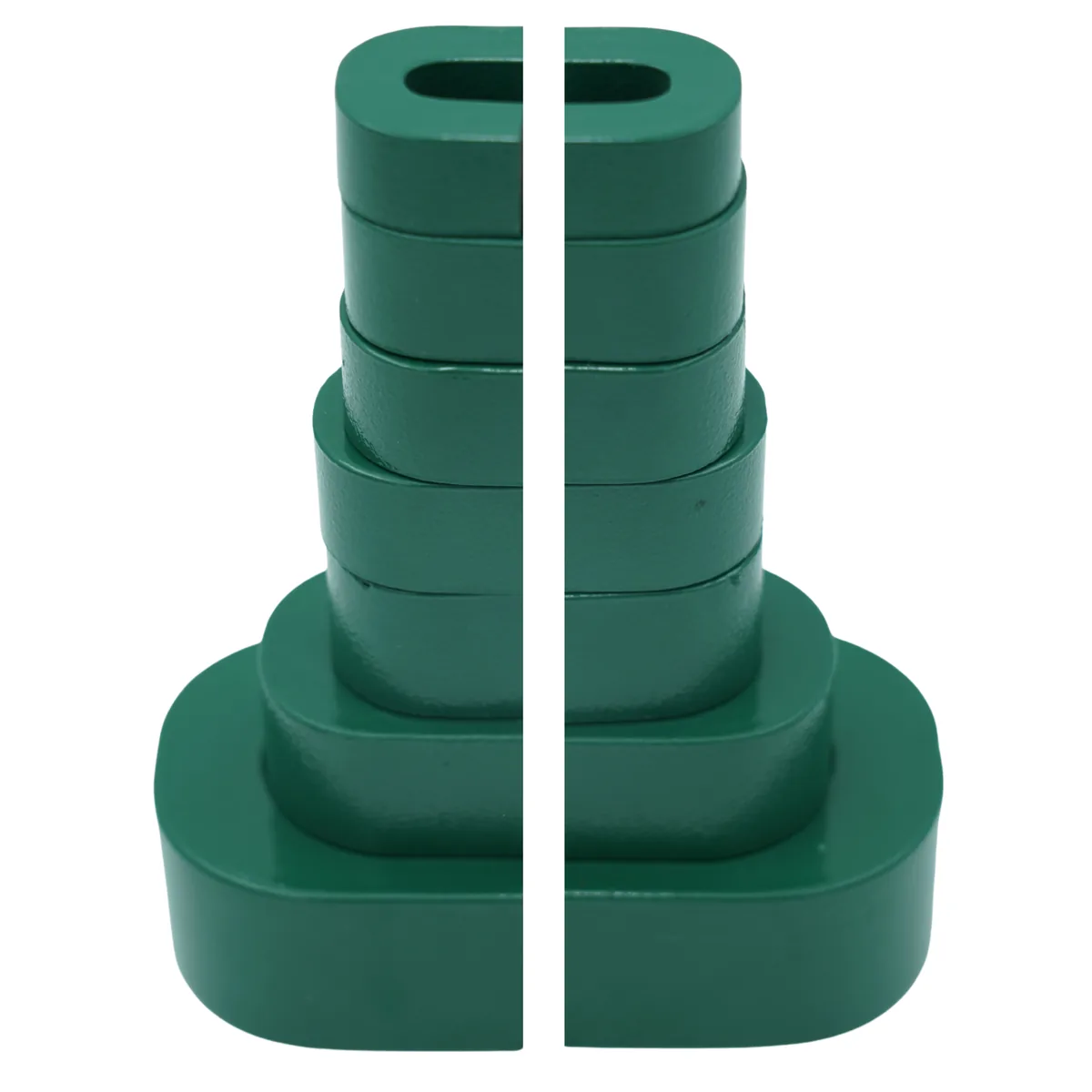
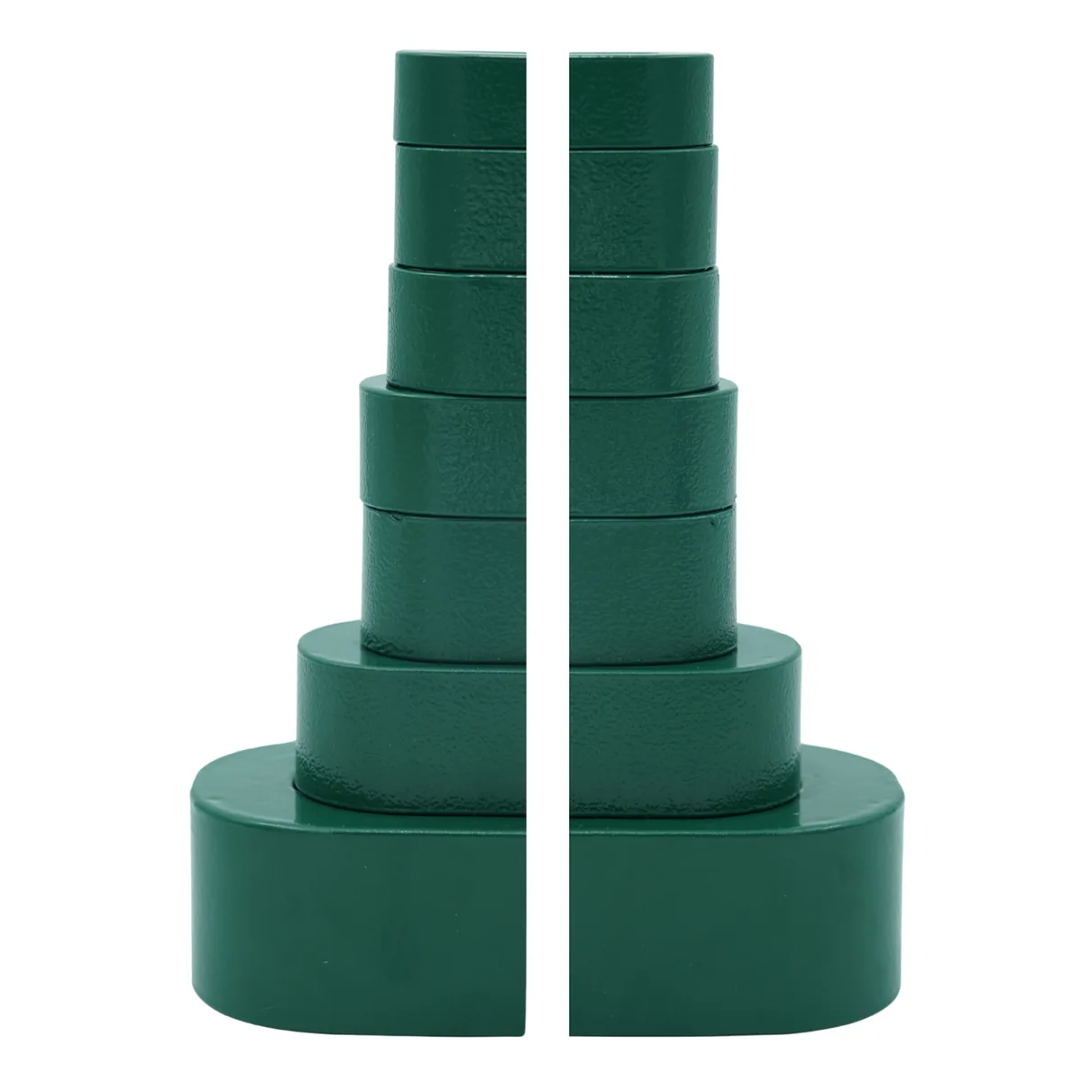
Most magnetics programs do not start with one perfect SKU. They start with a nearby Ae, a first winding, and a gap that is probably wrong. Designers then climb: more copper, a different spacer, the next core up the stack. That is why we photograph nanocrystalline cut cores as a tower. Small pairs at the top for LED, adapter, and aux chokes. Production sizes at the base for EV, solar, and industrial reactors. Same coating, same cut, different Ae.
Cut core vs toroid: pick the path you can manufacture
If the magnetic job is a common-mode choke or a metering CT, stay on a nanocrystalline toroidal core. You want a continuous high-μ path, not a cut. If the job is a PFC inductor, DC reactor, or a bobbin-wound HF transformer, the cut core is the practical part.
| Need | Cut core (C-core) | Closed toroid |
|---|---|---|
| Bobbin, Litz, or copper foil | Wind the coil, drop it over the legs | Hand-thread or a toroid winder |
| Controlled air gap / DC bias | Spacer or factory gap sets assembled inductance | Only if you cut or under-use the core |
| Re-open after a winding change | Yes | Usually destroy the coil |
| Highest un-gapped permeability | No. The cut is a gap | Yes. Better for CMC and CT |
| Clamp and acoustic noise | Mating faces and clamp must be consistent | Less sensitive to a split joint |
1. Openable geometry: wind the coil, then assemble the core
Toroids force the wire through the window. Heavy magnet wire, Litz, and foil make that miserable on a lab bench, and they lock you into toroidal winding gear on the production line.
A C-core splits into two halves. You wind on a pre-formed bobbin (or a simple winding form) on a standard machine, then assemble the halves through the coil. If the first AL reading is low, the insulation needs another wrap, or the prototype needs extra primary turns, you unclamp the core. The winding survives. That loop is why cut cores show up in R&D kits: a three-turn change is an afternoon, not a re-wound toroid. Window length and height (c and e on CCNC drawings) set how much copper you can actually put on the bobbin.
For size-ladder packs with gap spacers, start with nanocrystalline core kits for design engineers. After one size wins, reorder that CCNC SKU in pack quantity.
2. Air-gap control and DC bias
PFC boost inductors, EV onboard charger reactors, and solar string inverter stages carry a DC component. A closed high-μ toroid will saturate unless you gap it or run it at a fraction of its flux capability.
The cut already gives you a joint you can control:
- As-shipped matched faces for a low-reluctance pair (published AL).
- A precision spacer on the bench while you hunt the AL that stays linear at peak current.
- A factory gap once inductance, DC bias, and acoustic limits are locked.
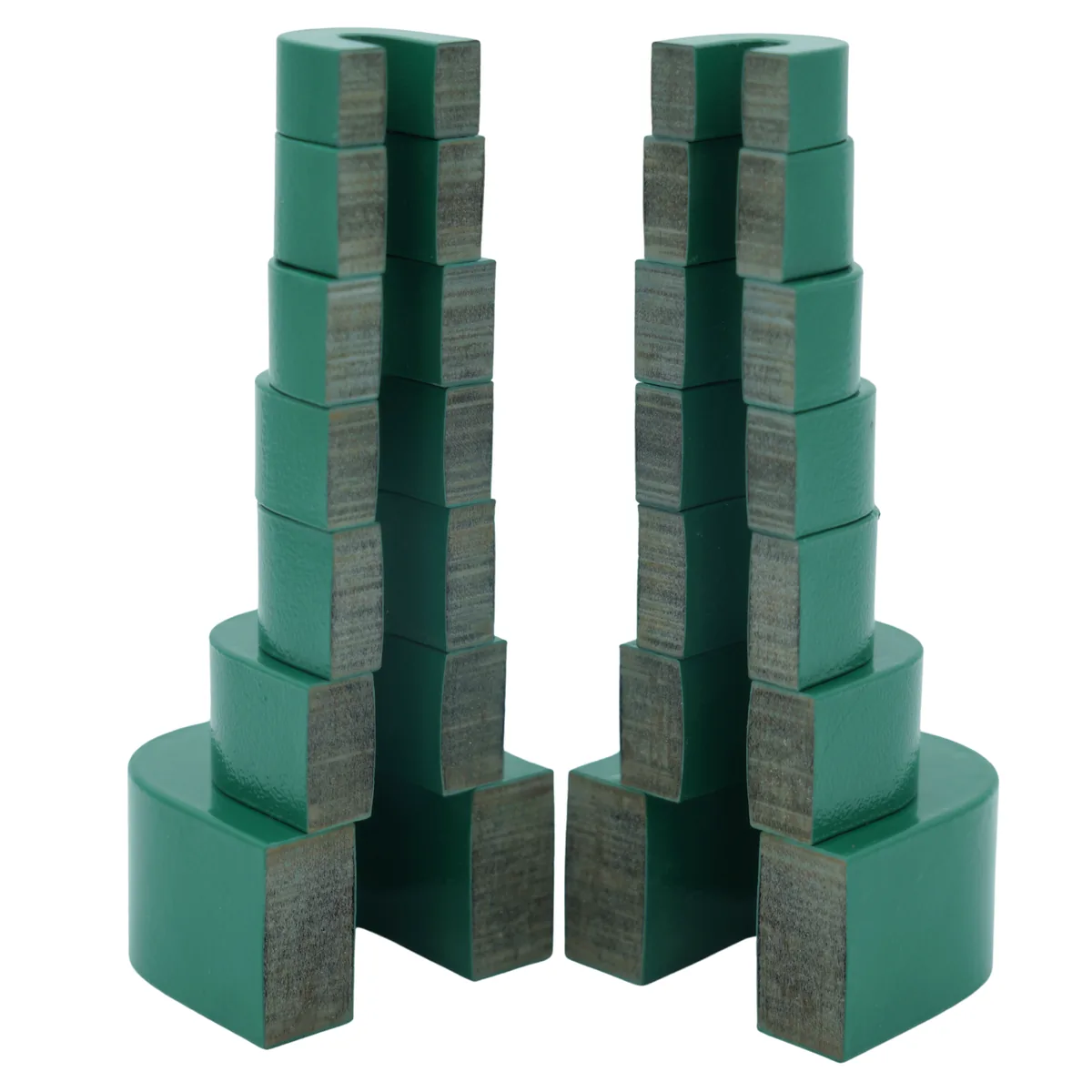
Treat the gap as a design variable, not a defect. It sets assembled inductance, delays saturation, and stores energy in the inductor. It also makes AL sensitive to clamp force and face cleanliness. Specify how the pair is held (band, clip, or fixture) and keep that method the same from prototype to production.
Custom gap, stack height, and measured inductance targets are quoted from frequency, inductance, DC bias, and thermal limits. Request a quote with those four numbers. Do not send “need a C-core” with no bias.
3. Where the material actually pays
HF / medium-frequency transformers. Higher Bs than ferrite means a smaller core cross-section (Ae) for the same volt-seconds, which can cut copper length and footprint. Validate loss at the real flux, frequency, and temperature. See nanocrystalline vs CRGO vs ferrite for the material bands, and EV charger core selection when the topology is an OBC or DCFC transformer.
PFC boost inductors and DC reactors. This is the cut core’s home turf: gapped energy storage, bobbin winding, and nanocrystalline loss in the tens of kHz. Ferrite often needs more Ae under bias. CRGO is the wrong frequency class.
EV chargers and solar inverters. Published CCNC magnetics cover about -40°C to +150°C, with Curie temperature 560°C. Stay inside the powder-coating temperature class for continuous duty, and budget hotspot rise from copper plus core loss in the clamp and bobbin, not just ambient.
Do not stretch this list to EMI common-mode chokes. A gapped C-core is a different component from a closed high-μ toroid.
Stocked CCNC sizes you can buy now
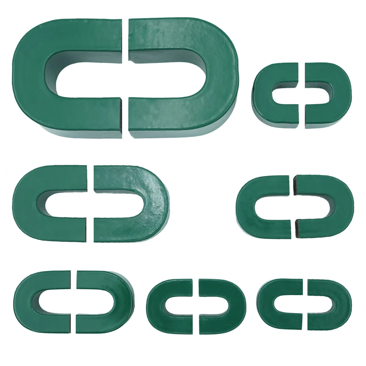
CenturaCores publishes seven powder-coated nanocrystalline cut cores with a–f×R geometry, Ae/Le, and AL at 1 kHz / 10 kHz / 100 kHz. a is tongue width, b is build, c is window length, d is strip width, e is window height, f is overall length, R is corner radius. Magnetic calculations should use published Ae and Le, not a tape-measure of the coating.
| SKU | Mass | Ae | Typical use |
|---|---|---|---|
| CCNC-09-09-32-15-28-51-002-MFGR | 90 g | 1.24 cm² | LED / aux SMPS, low-power PFC |
| CCNC-10-10-33-20-31-53-002-MFGR | 135 g | 1.60 cm² | Adapter and DC-DC chokes |
| CCNC-11-12P5-29P5-20-35-53-002-MFGR | 160 g | 2.00 cm² | Compact PFC boost inductors |
| CCNC-11-13-40-20-35P5-63-002-MFGR | 170 g | 1.80 cm² | DC filter and micro-inverter chokes |
| CCNC-10P8-13-40P5-25-35P5-62-002-MFGR | 215 g | 2.30 cm² | PFC and DC-link reactors |
| CCNC-13-15-56-25-42-84-002-MFGR | 380 g | 3.60 cm² | Industrial PFC and DC reactors |
| CCNC-19-24-83-35-63P5-122-002-MFGR | 1.06 kg | 6.12 cm² | EV, solar, and UPS reactors |
Full photos, AL tables, and pack pricing live on the nanocrystalline cut cores collection.
From first winding to a production part
- Pick two or three nearby Ae values from the table, or a cut-core kit.
- Wind the bobbin as you intend to manufacture it (same wire, same fill, same insulation).
- Measure AL with the intended clamp. Change only the spacer until DC-bias inductance holds at peak current.
- Check temperature rise and audible noise at the real waveform. Nanocrystalline is brittle after anneal; do not over-clamp the coating into the joint.
- Freeze size, gap, and clamp method. Reorder that SKU, or send the locked inductance and gap to a custom quote.
Specification language for drawings, μ/AL test conditions, and acceptance tests lives in how to specify a custom nanocrystalline core.
Frequently asked questions
- When should I use a nanocrystalline cut core instead of a toroid?
- Choose a cut core when you need an openable path for a bobbin, Litz, or foil coil, or a controlled air gap for DC bias (PFC boost inductors, EV onboard charger reactors, solar and DC reactors). Use a closed nanocrystalline toroid for common-mode chokes and current transformers, where you want a continuous high-permeability path.
- Why are cut cores called the backbone of R&D prototyping?
- A C-core splits into two halves, so you wind the coil on a standard bobbin, assemble the core, measure, then reopen it to change turns, insulation, or gap spacers without scrapping the winding. The size ladder (small Ae at the top of the stack, production sizes at the base) is how most PFC and charger prototypes actually climb from first bench test to a locked SKU.
- Can CenturaCores customize the air gap on stocked cut cores?
- Yes. Stocked CCNC parts ship as matched cut pairs. Published AL is measured on the uncut closed core and is not an assembled-pair guarantee. For PFC, EV onboard charger reactors, and solar inverter stages, we quote custom gap, stack height, and measured inductance targets. Send frequency, inductance, DC bias, and thermal limits with the request.
- What does the published AL value mean for cut cores?
- Published AL is measured on the uncut single-piece core (closed magnetic path) at the stated frequency and flux. After cutting, assembled AL is not specified because it depends on joint tightness, clamp force, and any intentional gap. Size gapped designs from the intended gap, then verify L on the assembled inductor.
- How do nanocrystalline cut cores compare with ferrite on size?
- Saturation around 1.27 T versus ferrite around 0.4 T means less core cross-section (Ae) for the same volt-seconds, if core loss at your flux, frequency, and temperature still fits the thermal budget. Compare loss at the real operating point, not at a 50 Hz catalog figure.
- What temperature range do these powder-coated cut cores support?
- Published magnetics cover about -40°C to +150°C continuous working temperature, with Curie temperature 560°C. Stay inside the powder coating temperature class for continuous duty, and account for hotspot rise from copper and core loss in the clamp and bobbin.
Buy stocked cut cores
Matched CCNC pairs with published a–f geometry, AL, and production photos.
View cut coresStart with an R&D kit
Size-ladder packs with gap spacers so you can lock Ae and AL before a production order.
View prototyping kits